Just one of my major recent projects/ building process; but I thought it gives a good idea of me. I will a make a formal introduction when I get some free time.
But Anyways, Thanks for Stopping By My Portfolio Website!
Colorful project for homepage
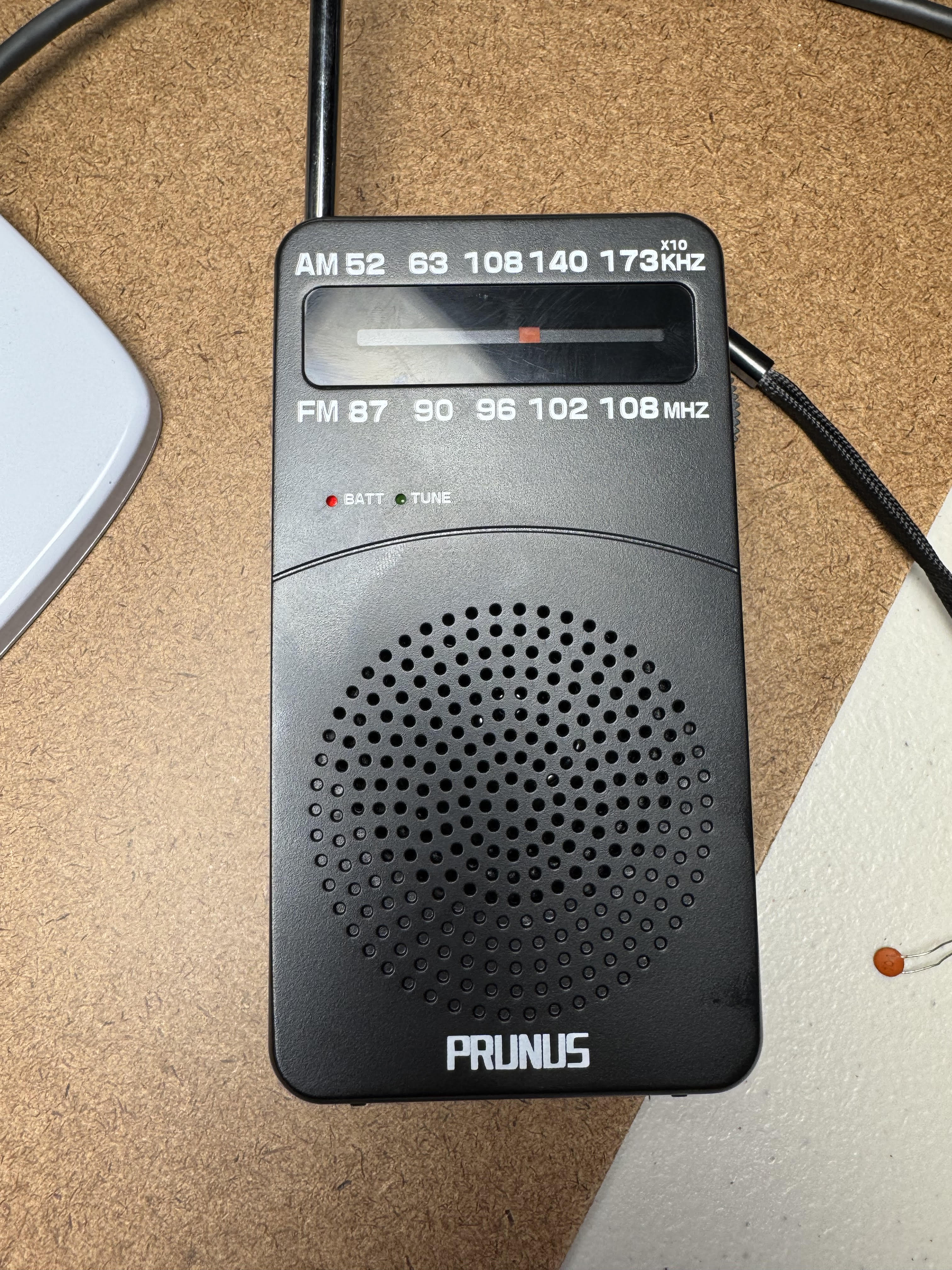
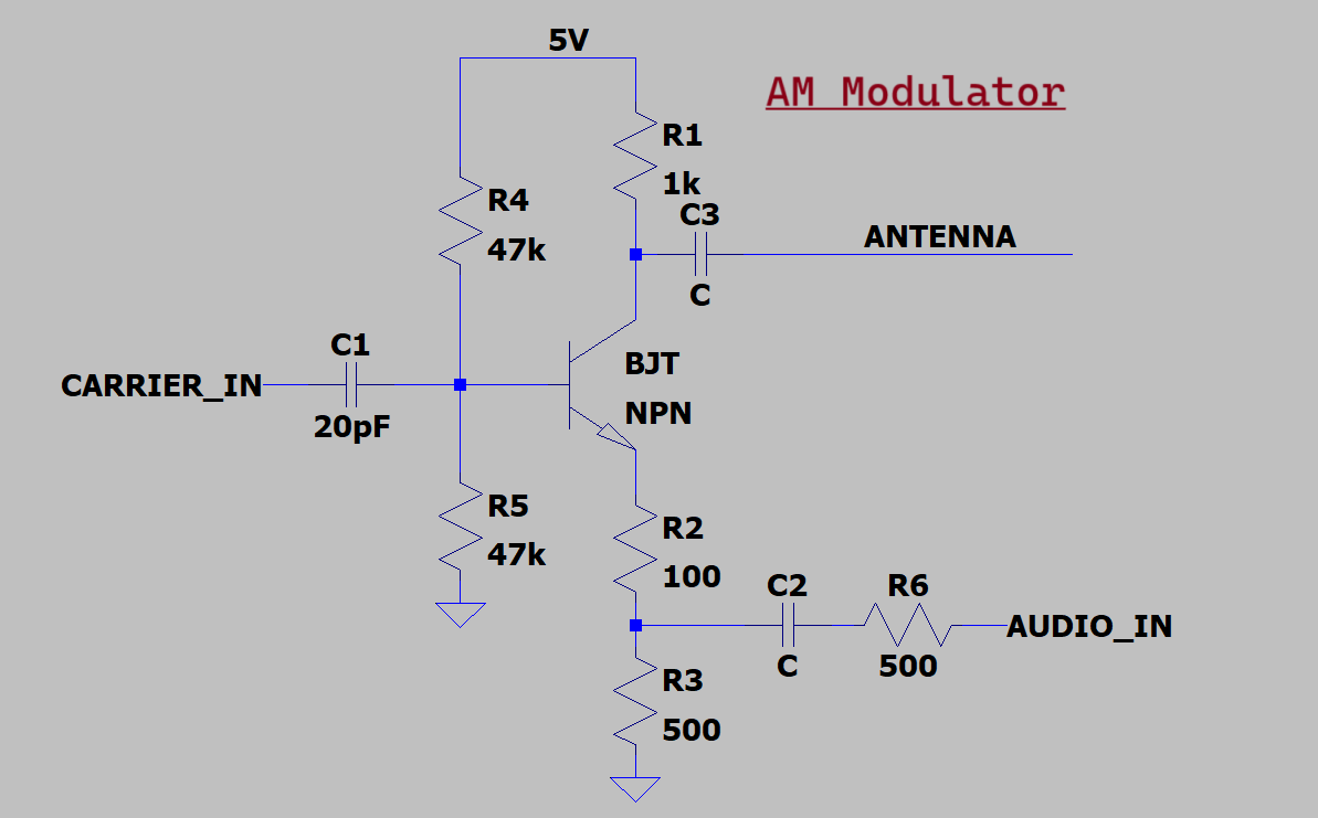
AM Radio Music Transmitter – Successful transmission, broadcast
Video
AM Transmitter Demonstration (Manhattan construction)
Overview
This is an AM transmitter I made. and I actually started working towards this a long time ago. I’ve had some people ask about my projects, and I think I should explain how they are interconnected. Someone had asked me if I was familiar with rf, which at the time I wasn’t. So I asked, what is Rf? -Well, all it is is an oscillating frequency. So I started there, with a very simple relaxation oscillator. I then worked myself up to higher-frequency circuits, and I learned a lot along the way. Finally, I made my first transmitter; and Rf circuit. I did this in about a month. Which consisted of a lot of time reading about different oscillator circuits, building each one. learning the difference between Hartley and Colpitts oscillators. When to use which.
I think my skillset has really grown, in a short period of time. it took a lot of perseverance, and even the times I thought I was going nowhere, I look back; and those times were often critical steps in my understanding. I look back, and many of the ideas I stated, or shared with others, I later successfully implemented
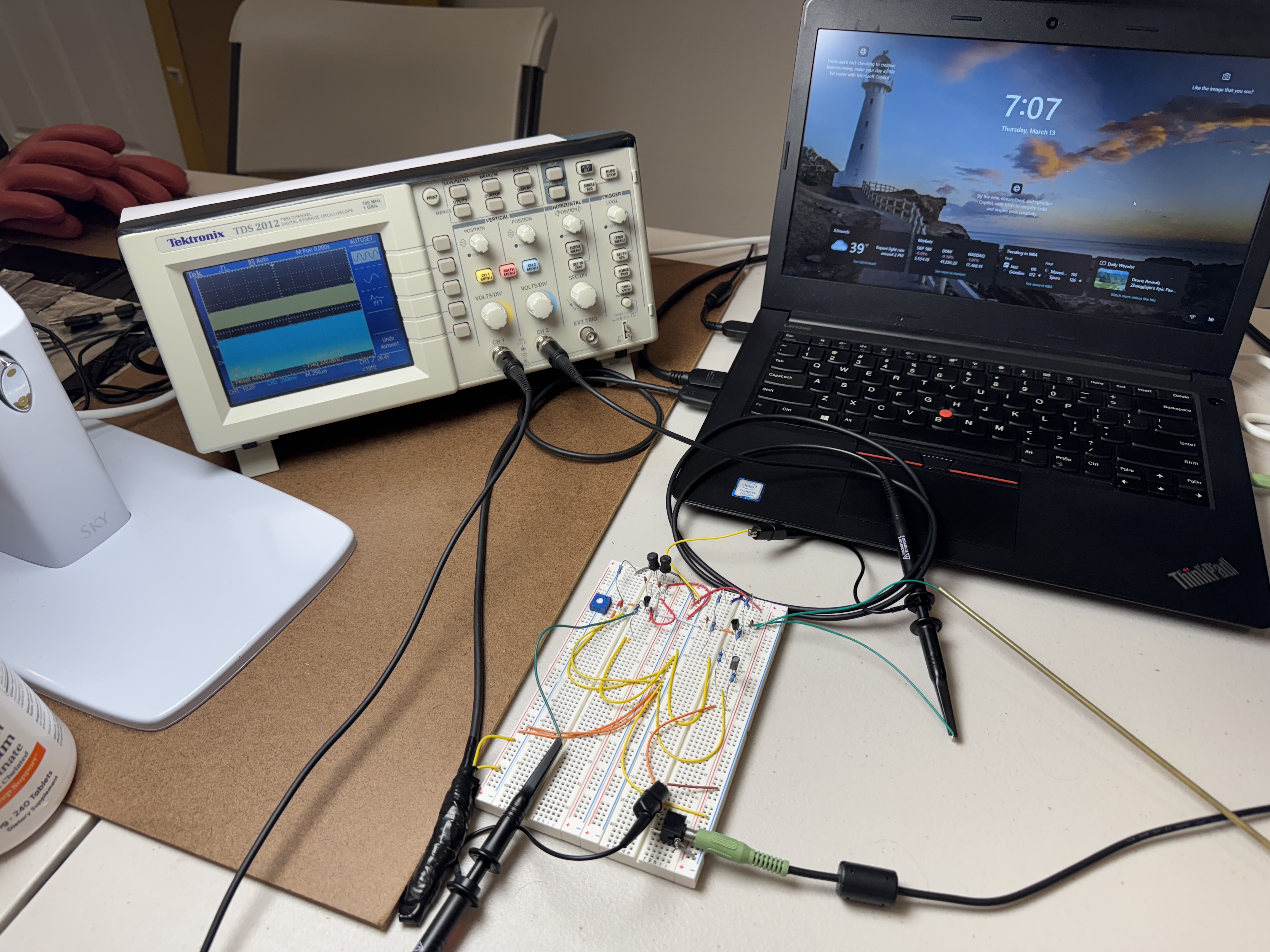
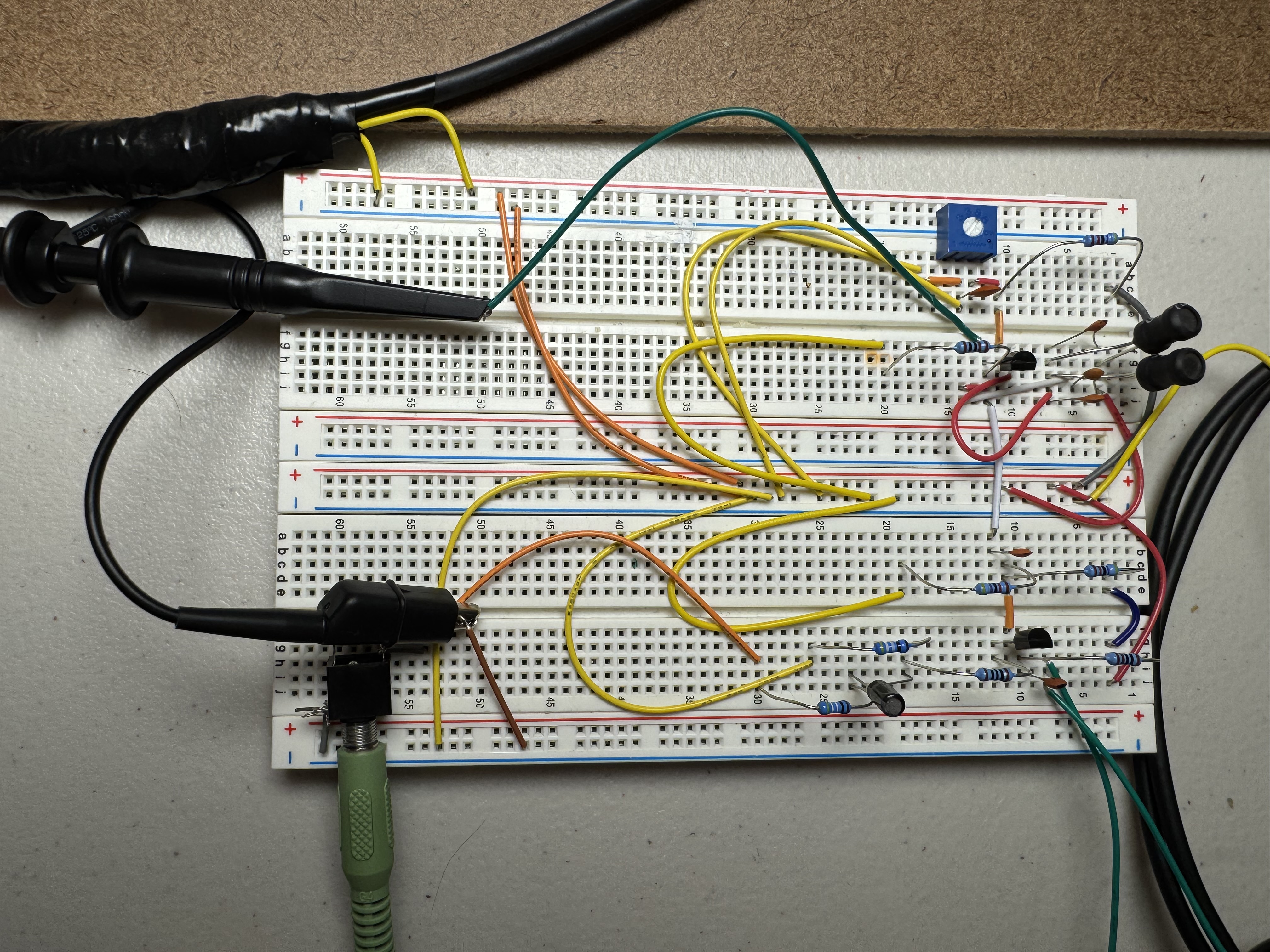
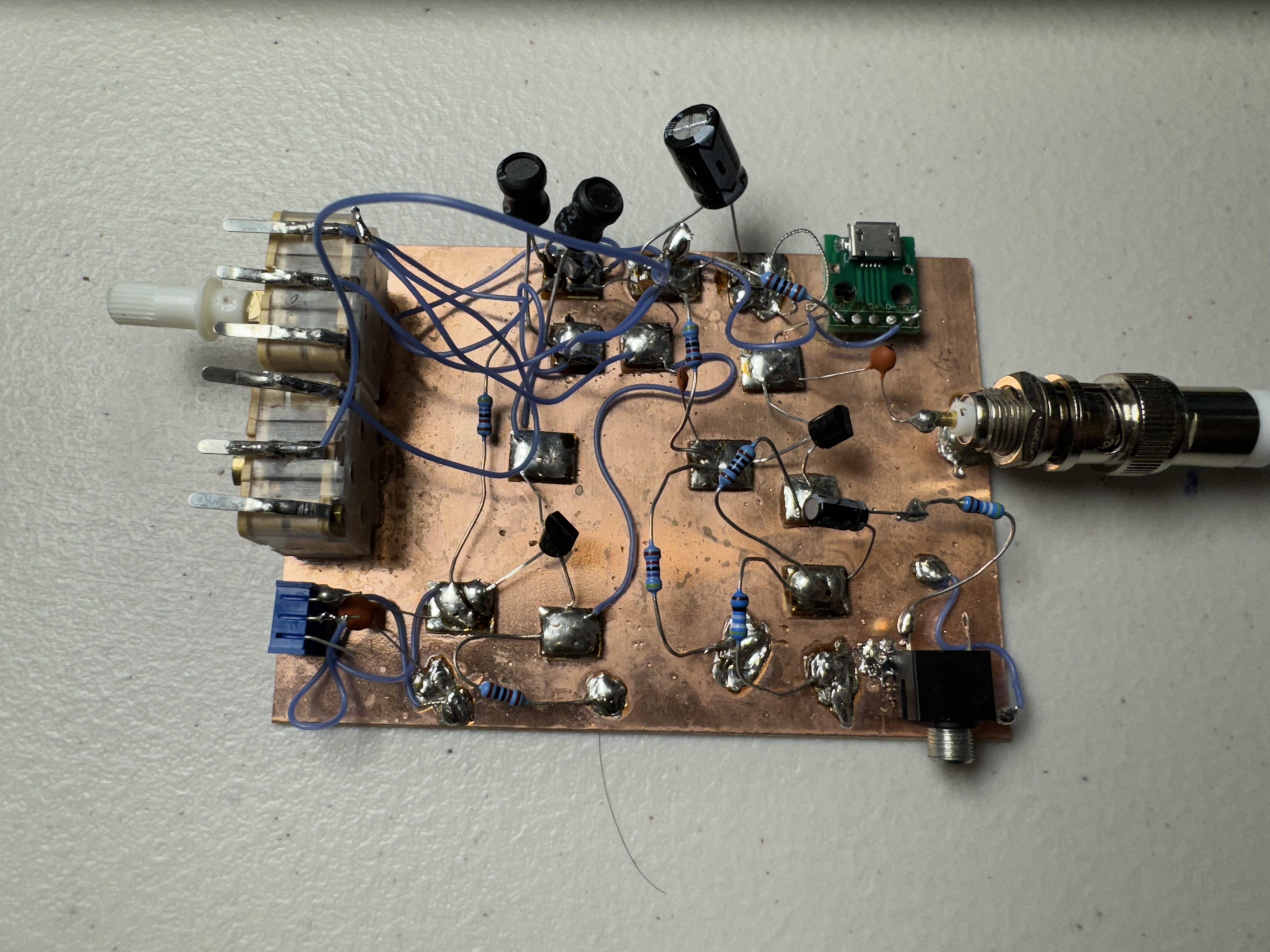
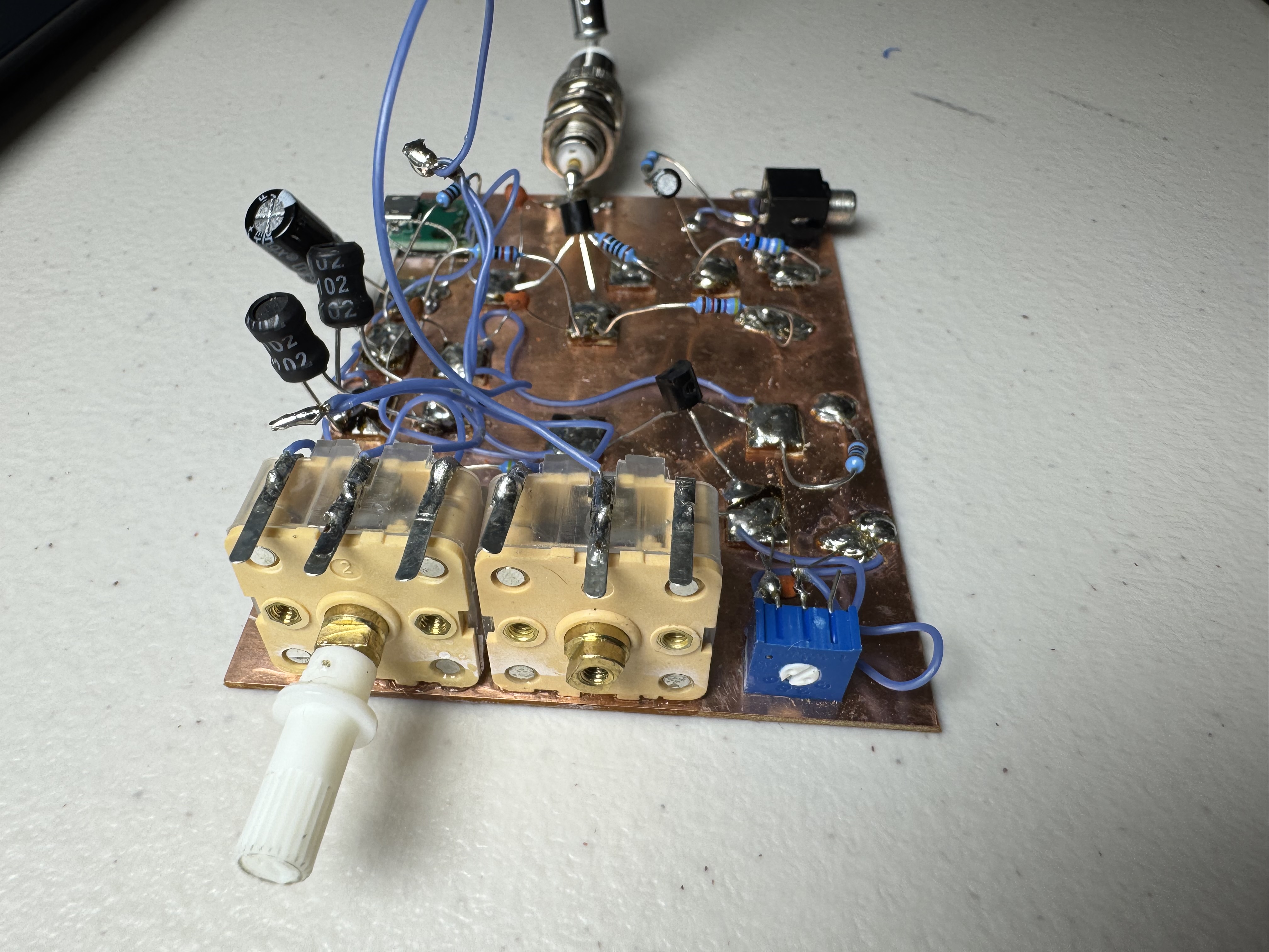
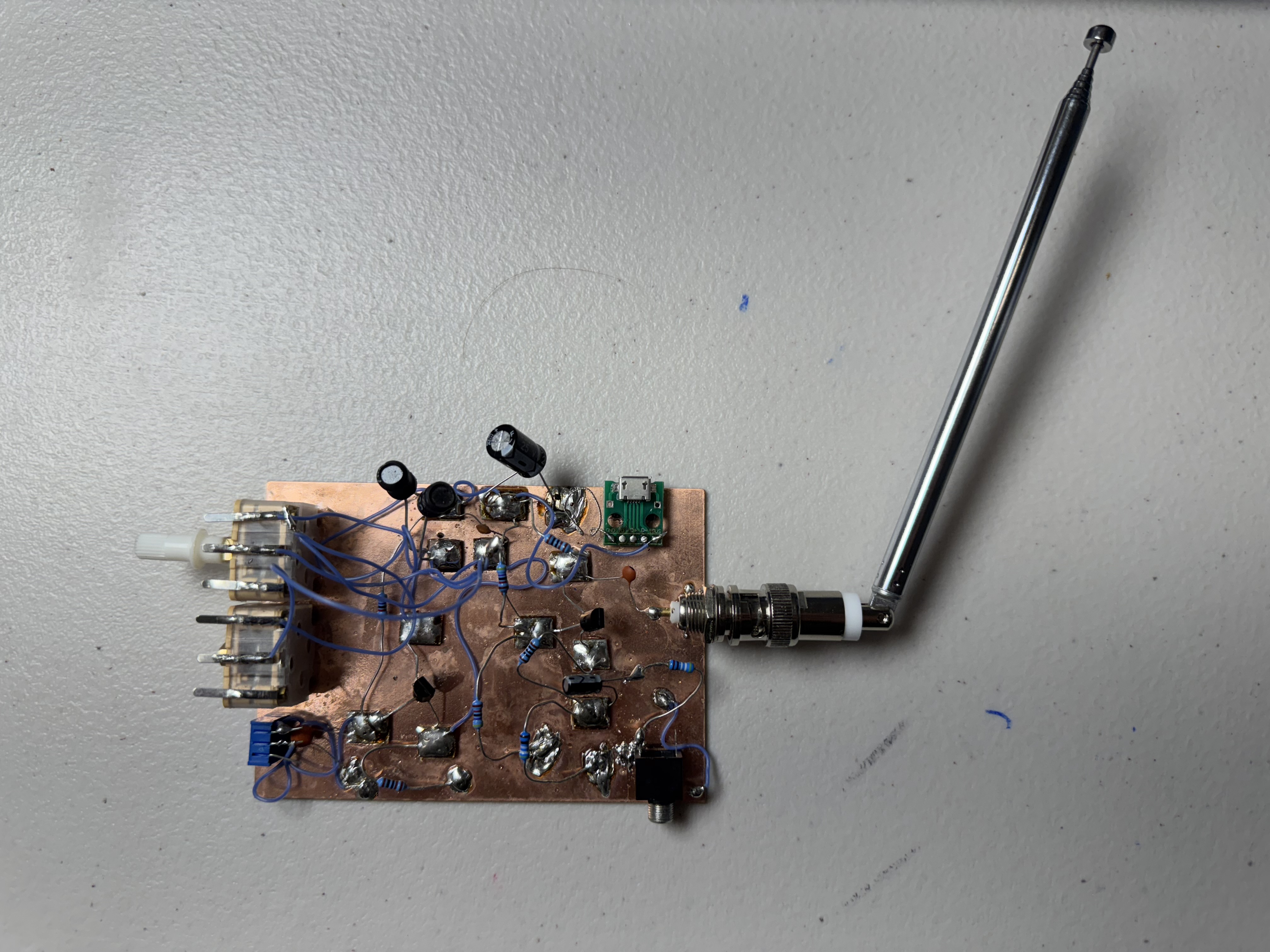
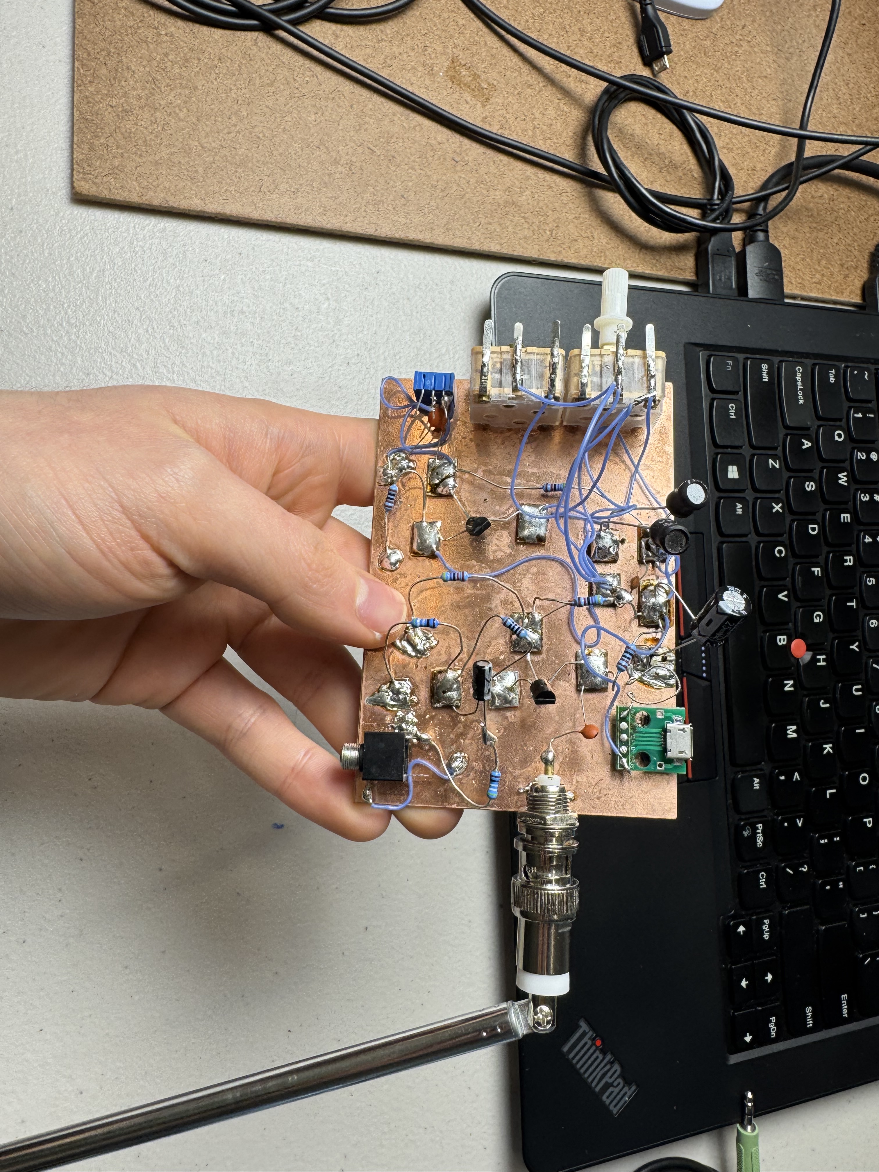
The images on the right, show the final version of my AM transmitter. It has an adjustable Colpitts oscillator located on the left side. This is done through a variable capacitor on the Tank circuit. This then feeds into a single transistor modulator on the right side. The modulator uses an audio input, to modulate the carrier wave’s amplitude. I then have a BNC connector to interface with the antenna. I learned these BNC connectors are actually the same connectors located on my oscilloscope.
Pictures
AM Transmitter
FM Radio Transmitter (~100feet transmission distance)
Video
Pictures
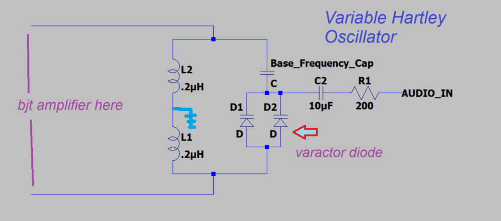
circuit diagram (Variable hartley oscillator, with varactor diode)
Design process
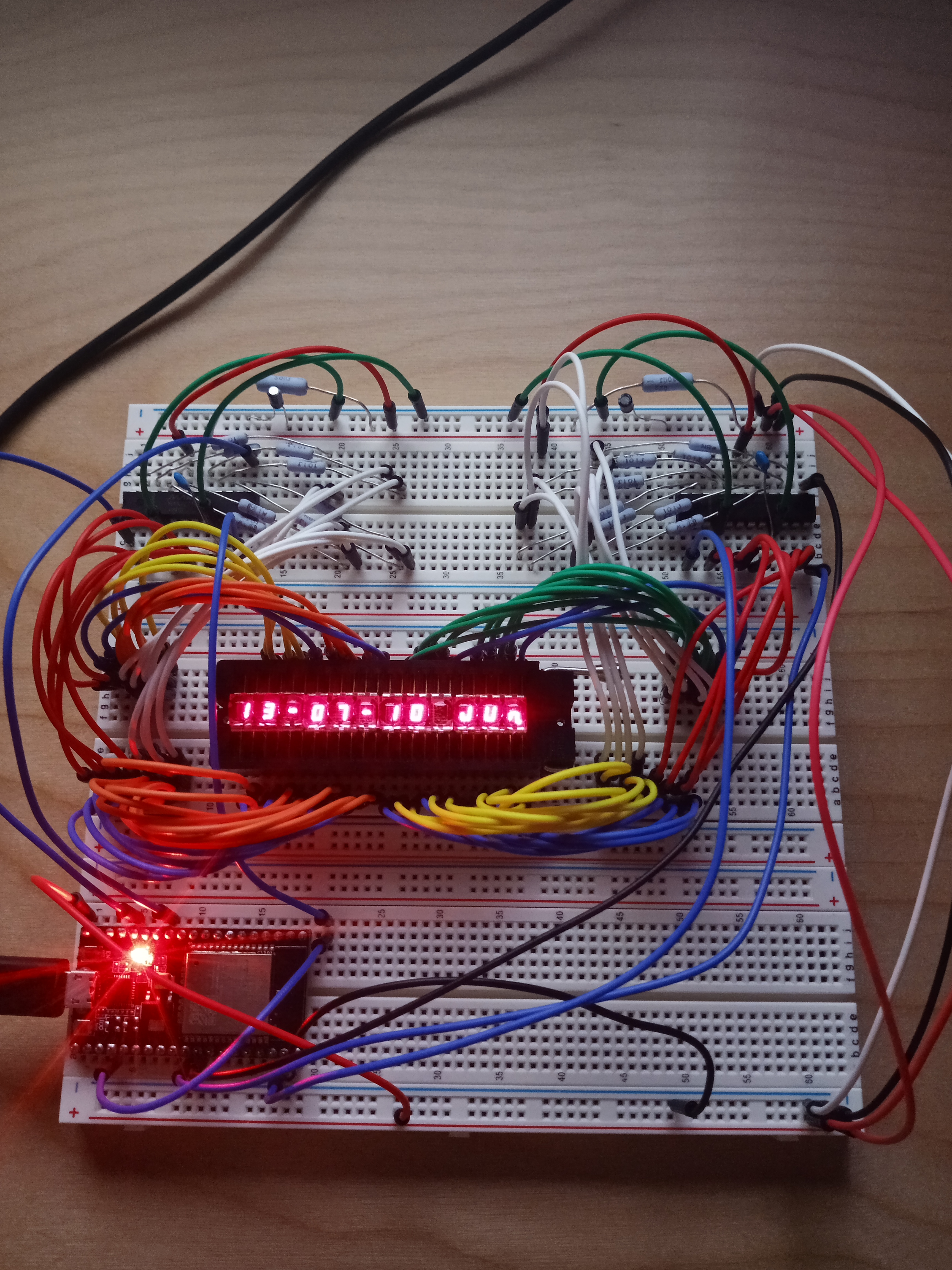
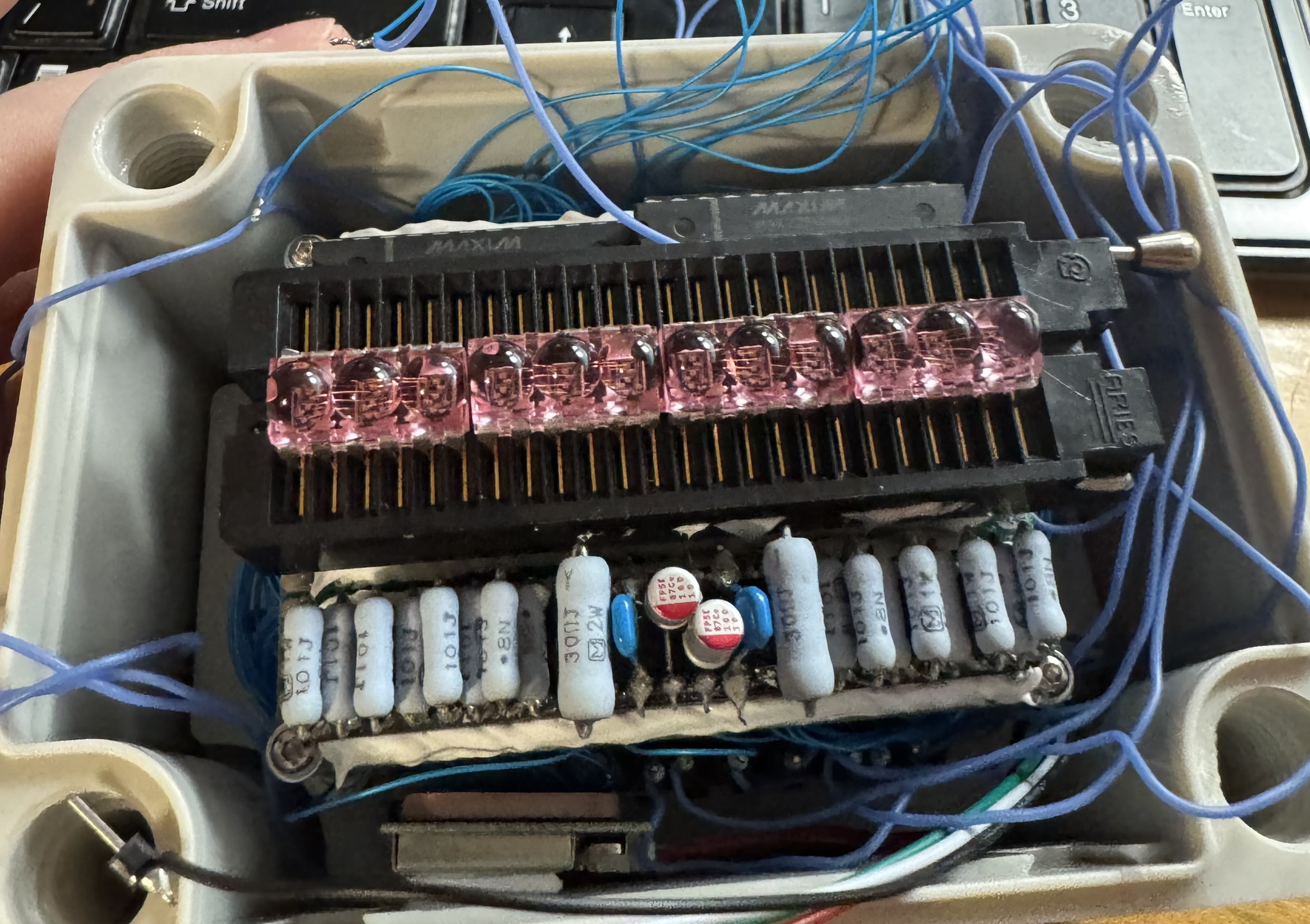
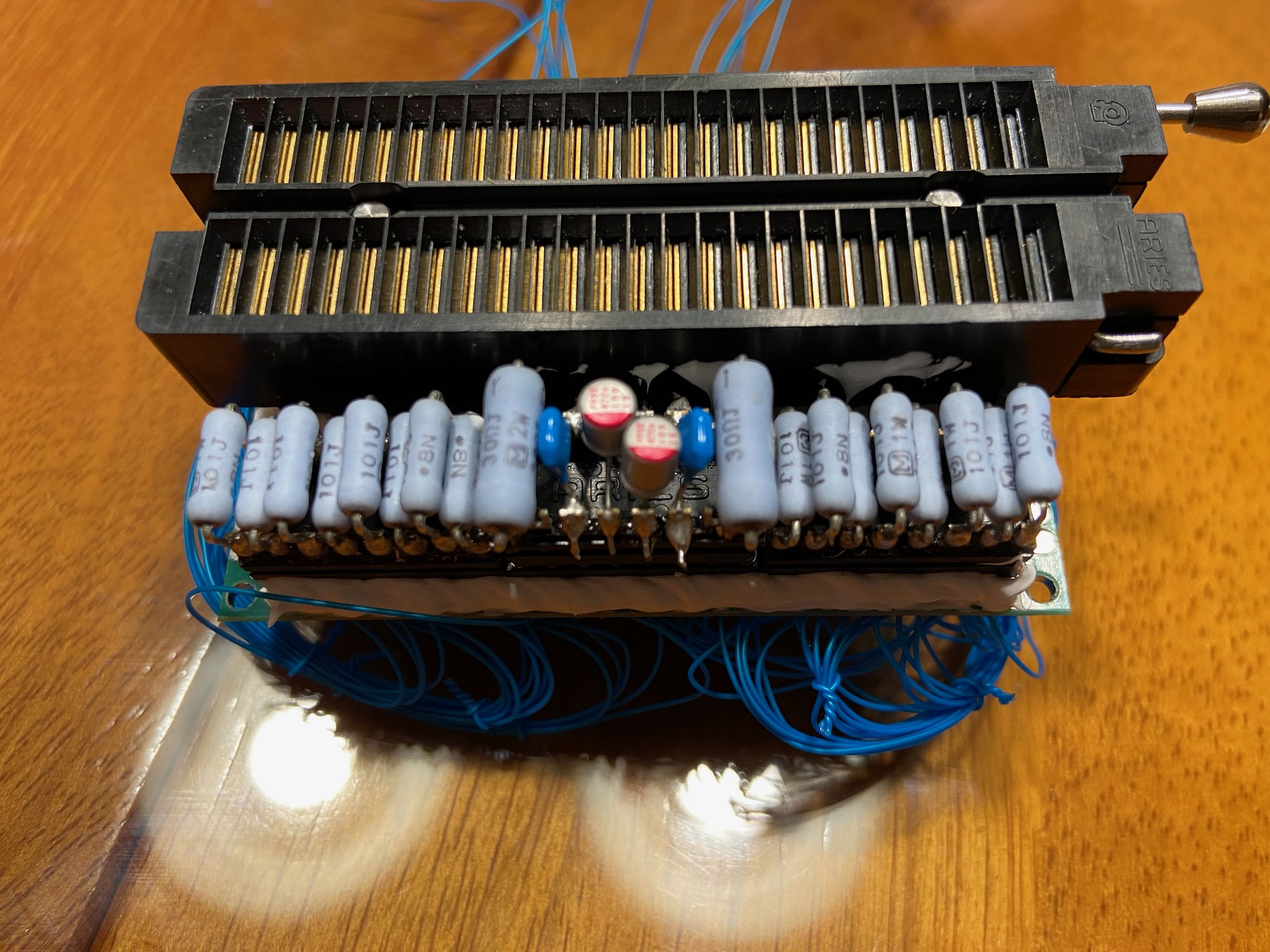
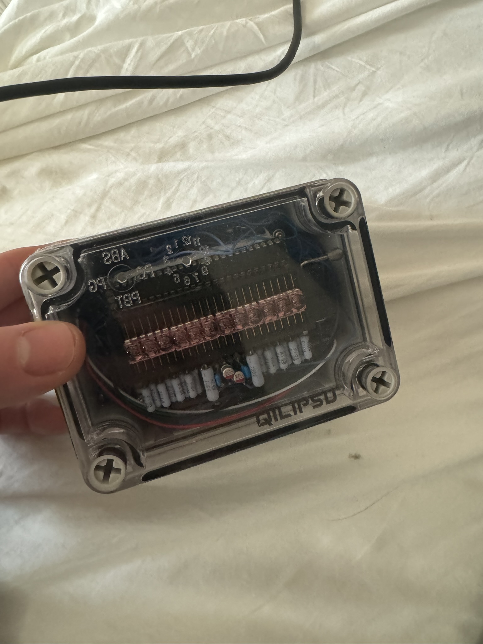
Real-Time Clock using HP Bubble Displays WIFI & ESP32 Multiplexed 7-Segment displays, with Maxim 7221 Display Drivers (SPI)
Video
Pictures
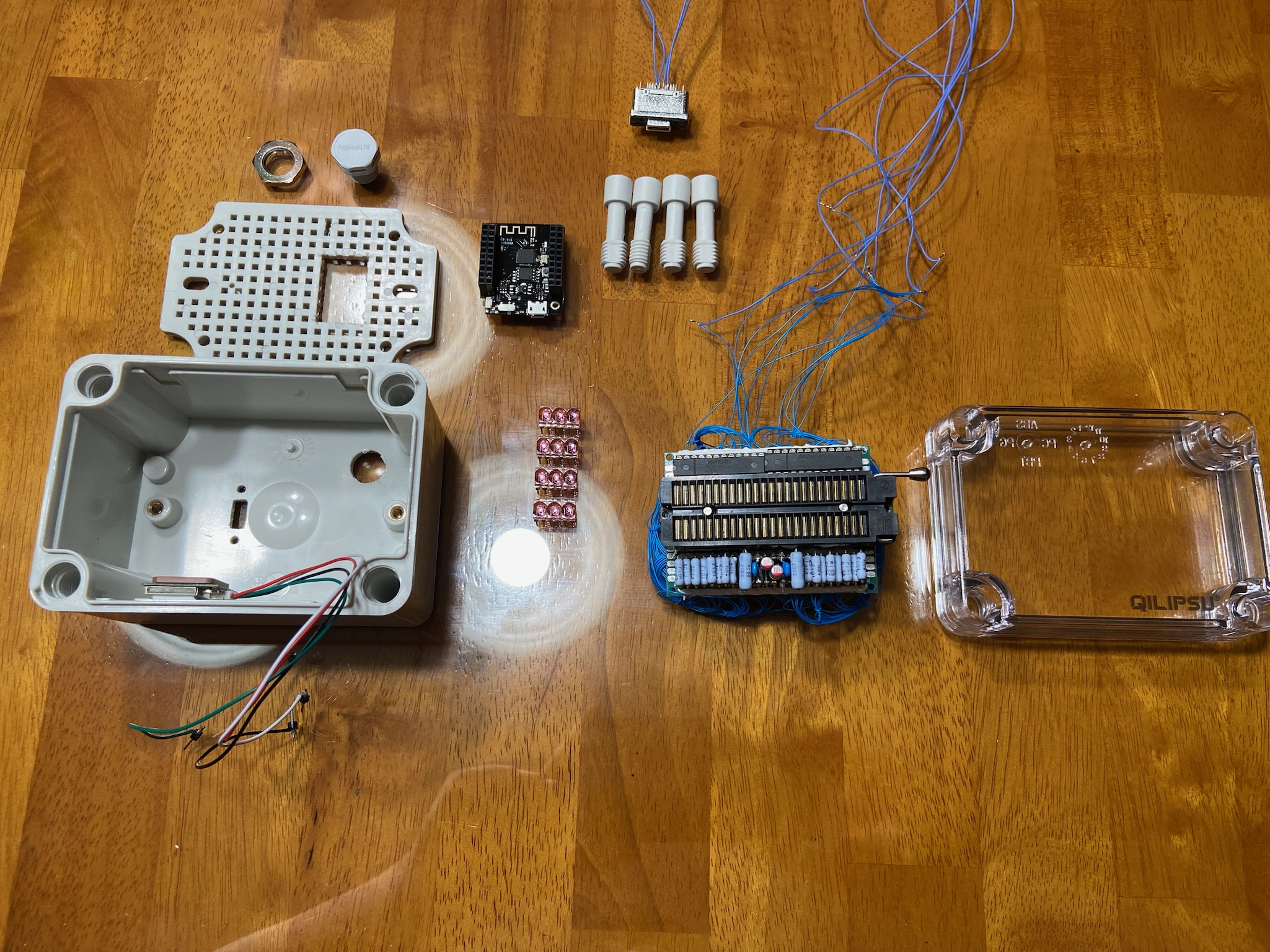
I learned of these small 7-segment displays, that Hewlett Packard made, back in the 1970s. What is so special, is they are the smallest displays you can purchase. These displays cost almost $100, and I decided to make a RTC centered around them. I honestly thought they were really cool. This circuit uses the common Maxim 7219/ 7221 display driver IC. It’s used to drive multiplexed displays (which these are). They are common cathode, so you will need a more advanced circuit to drive them.
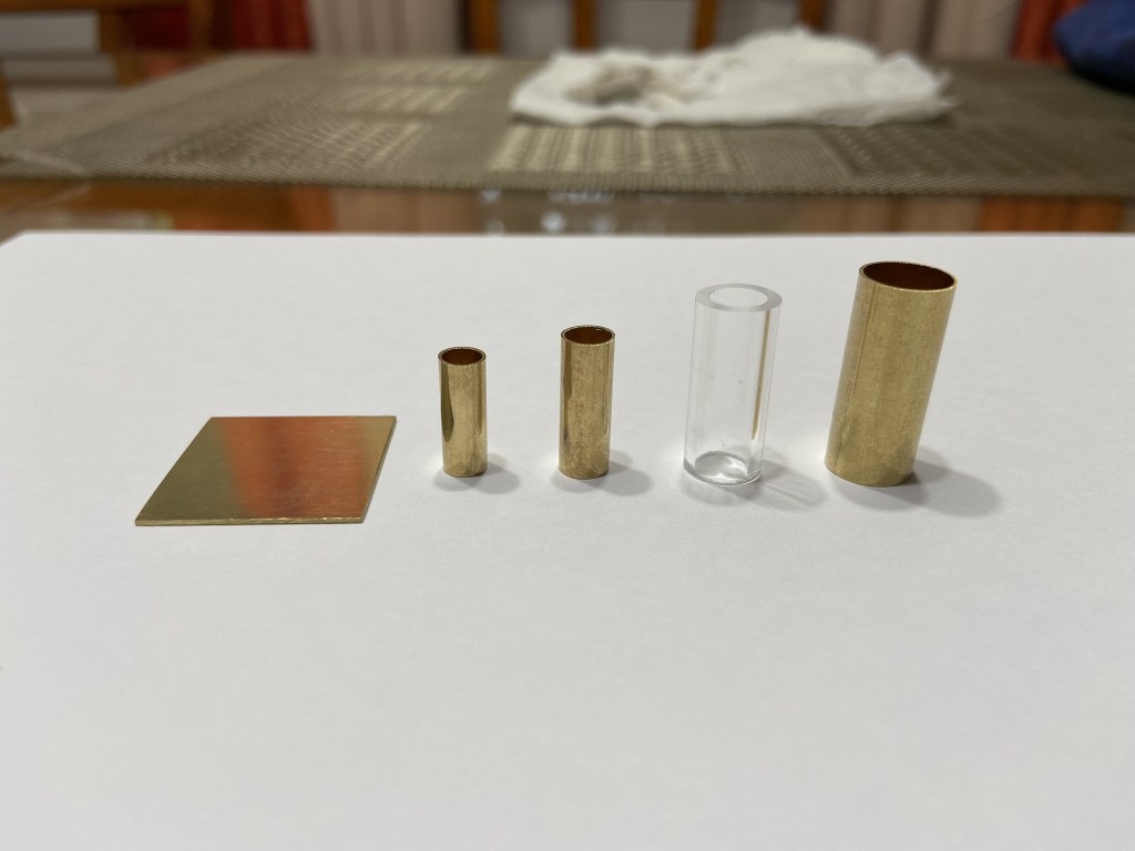
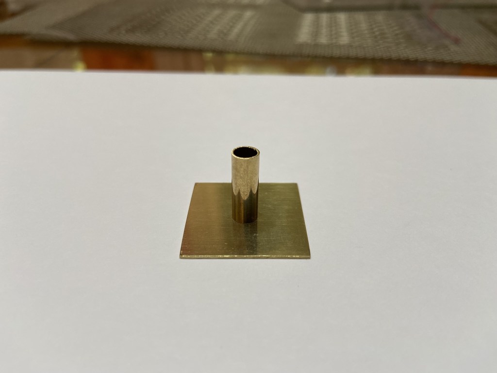
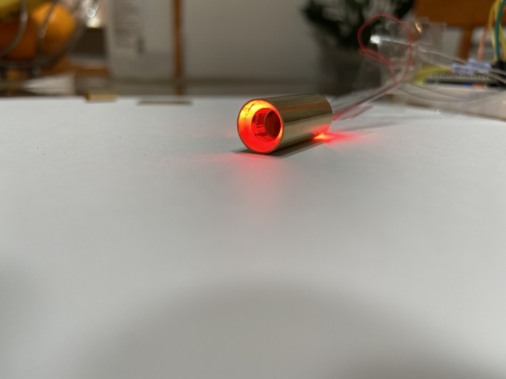
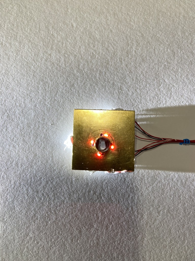
Fabrication of a High-Resolution, Small-Scale, Rotary Encoder Employing Polarizers
Video
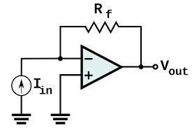
This is a rotary encoder I made, that uses light as an output. Basically, it will produce an oscillating light intensity at the output. The following circuit, was involved in interpreting this output, and converting it to a sinusoidal wave for position. The circuit I used is called a transimpedance amplifier; and it’s usually used for photodiodes.
Basic TIA circuit
I did learn some things after this. I used this basic circuit in my initial version of the encoder. I learned it is best to bias one input slightly. So that the TIA is not operating from + supply, to 0V. Apparently Op-Amps don’t usually truly operate from rail-to-rail. Also, it is good to have some margin. You don’t want to start your measurement from 0V, because the photodiode will have inherent “dark current”. So current will pass, even when it is not sensing. a small bias also avoids this issue, when the diode is at near 0 sensing.
Pictures
High-Gain Transimpedance Amplifier
Video
Pictures
I wanted to make a high-gain version of this TIA circuit. This involves multiple op amps, and also different kinds of op amps. For example, the one used for the initial transimpedance amp, is a decompensated op amp. Meaning it has fast response, but will become unstable at gains less than 10; according to the datasheet. A decompensated op amp works well for this TIA and photodiode circuit, where a high gain is common. However, the op amp used on the final portion, is a unity-gain stable op amp, meaning it can be used in a unity gain configuration, and stay stable. So sometimes, you will have to pick a variety of op amps, and familiarize yourself with the different kinds.
Also, all decompensated, and compensated means. Is that, if it is compensated, it will have some kind of capacitor built in, that prevents ringing/ instability. You can externally compensate an op amp, and the data sheet will usually provide the calculations necessary, to calculate the capacitor needed.
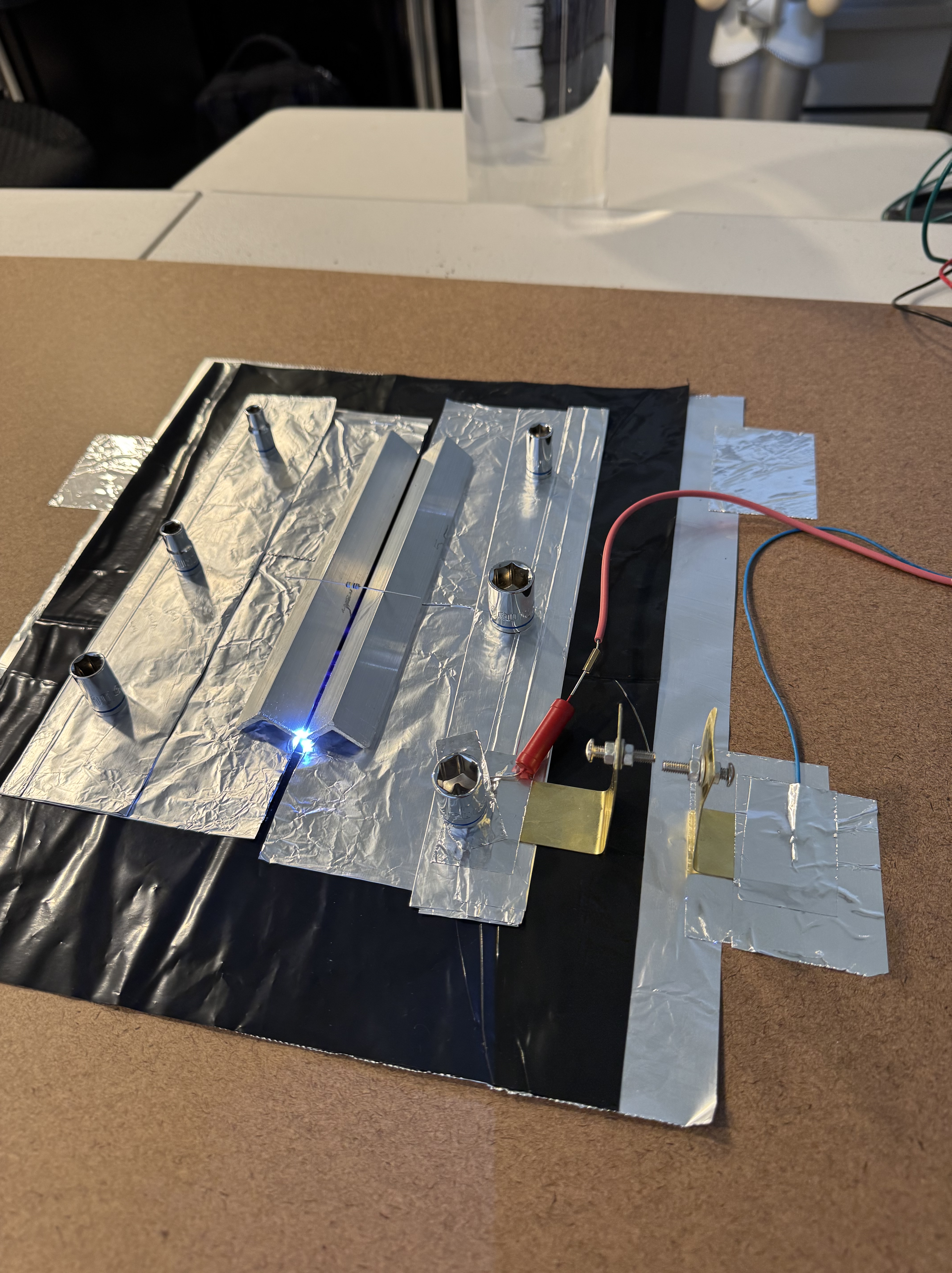
I know this sounds, maybe a bit unusual. But the way this laser operates, reminded me a lot of my oscillator projects. It has a charging resistor, that determines the rate of charge. and a capacitor that charges. It is like a RC circuit. In operation, it does oscillate at a certain frequency, which is determined by your spark gap.
Pictures
This is a gas laser, that functions by exciting nitrogen. There is a high voltage created in the laser channel, or gap. The nitrogen in the air then absorbs the energy. When the nitrogen collapses, and moves back down to its original state, it emits UV light. This is referred to as a ‘self terminating’ laser. This is one of the simplest gas lasers you can make, and provides a very good basis if you are looking into understanding gas lasers better. This could be referred to as a “pulsed laser”.
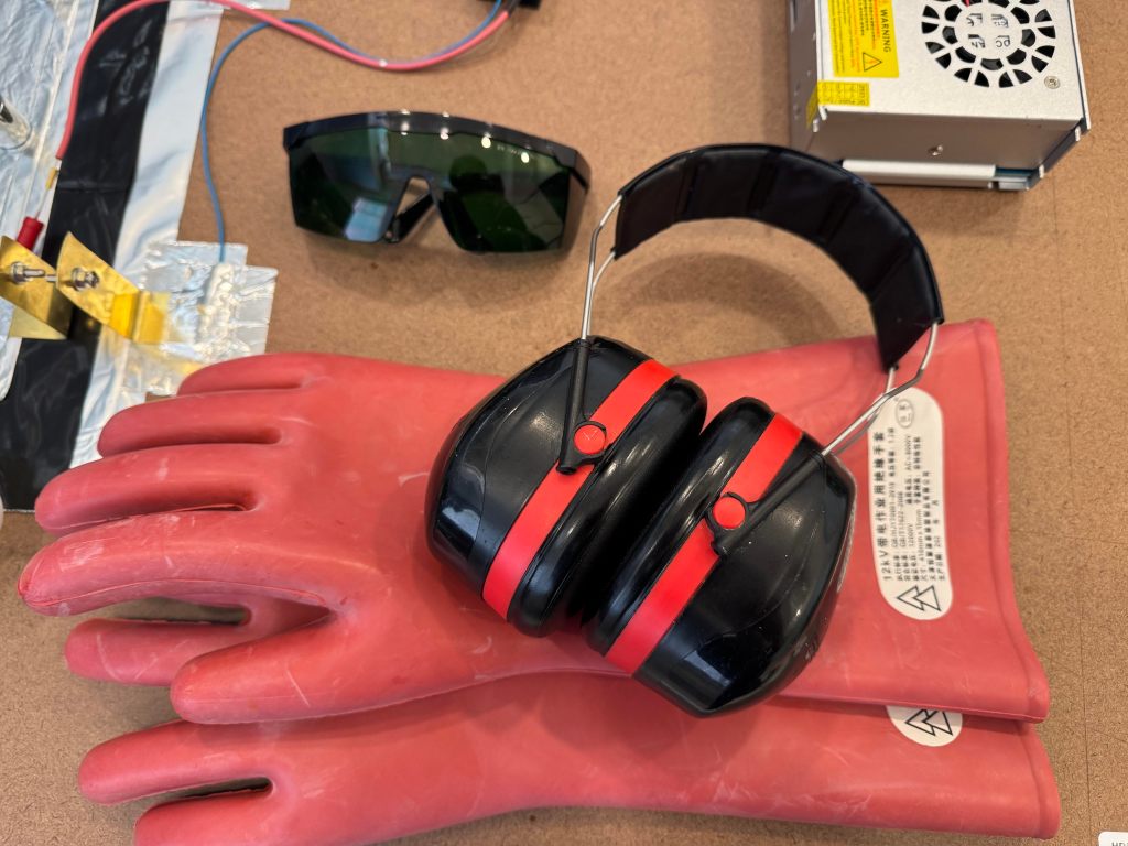
Safety Equipment
Variable Frequency, NPN Relaxation Oscillator
Video
This is a variable oscillator I made, that uses a single NPN transistor to create a relaxation oscillator. I did learn a lot, by changing different parts of the original design. For example, I drove an LED, a motor, and a speaker – all with my oscillator circuit. and I learned how to vary the frequency; by applying different capacitors, and resistor values in the circuit. If you do drive higher loads, it is a bit more complicated, and you might need a follower, or buffer on the output. Or you risk over loading the oscillator.
Pictures
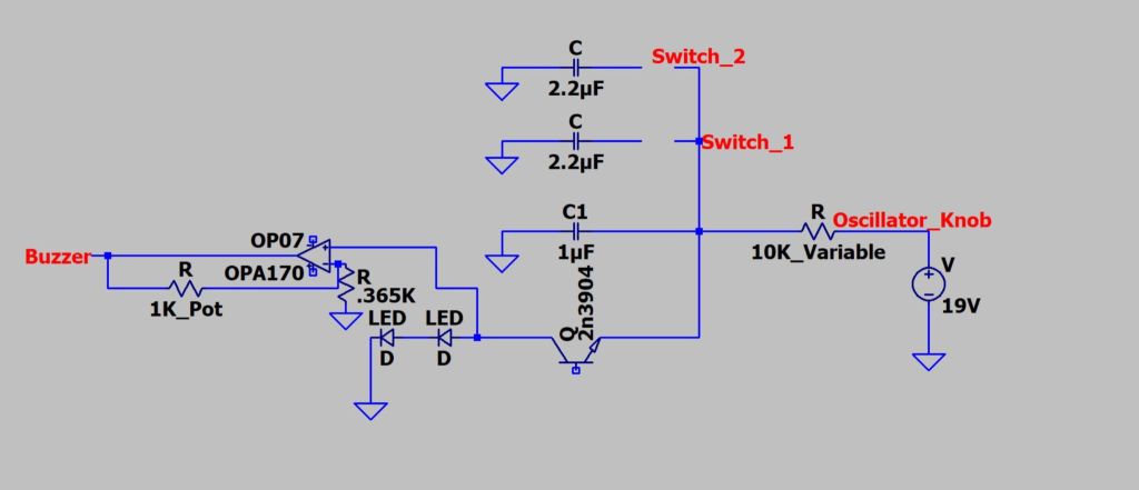
In my earlier version, when I tried using the lm741, it might have prevented the audible and variable output I am getting in this design. I am using a newer op amp here, and it is capable of higher frequencies compared to the lm741. That may have been a limiting factor previously. This op amp also supports up to 36 volts on the power inputs, and my oscillator took about 19V; so it is nice, because I can just hook the op amp up to the existing power, there is no need for an additional component. This is just a general op amp from Texas Instruments. It is the OPA170.
I tried finding variable capacitors, but I suppose they are not as common as they were, when radio was popular. Here, I used some basic switches and capacitors, to create different frequency ‘levels’. This worked okay to create some different frequencies.
Esaki Oscillator – Flasher circuit
Video
This is the main component of my variable oscillator. This is where the oscillations are created. However, from these examples I saw online. This is a very common circuit, but I haven’t seen anyone turn it into a frequency generator, to generate different tones. It was kind of fun getting to explore the different uses of this originally simple concept.
I even drove a motor at one point. Driving loads like that, require switching the op amp buffer, for a transistor instead. The transistor can provide more current, than the buffer op amp can. I also learned you will need some protection diodes, if you are driving inductive loads like motors. They are called snubber or fly-back diodes
Pictures
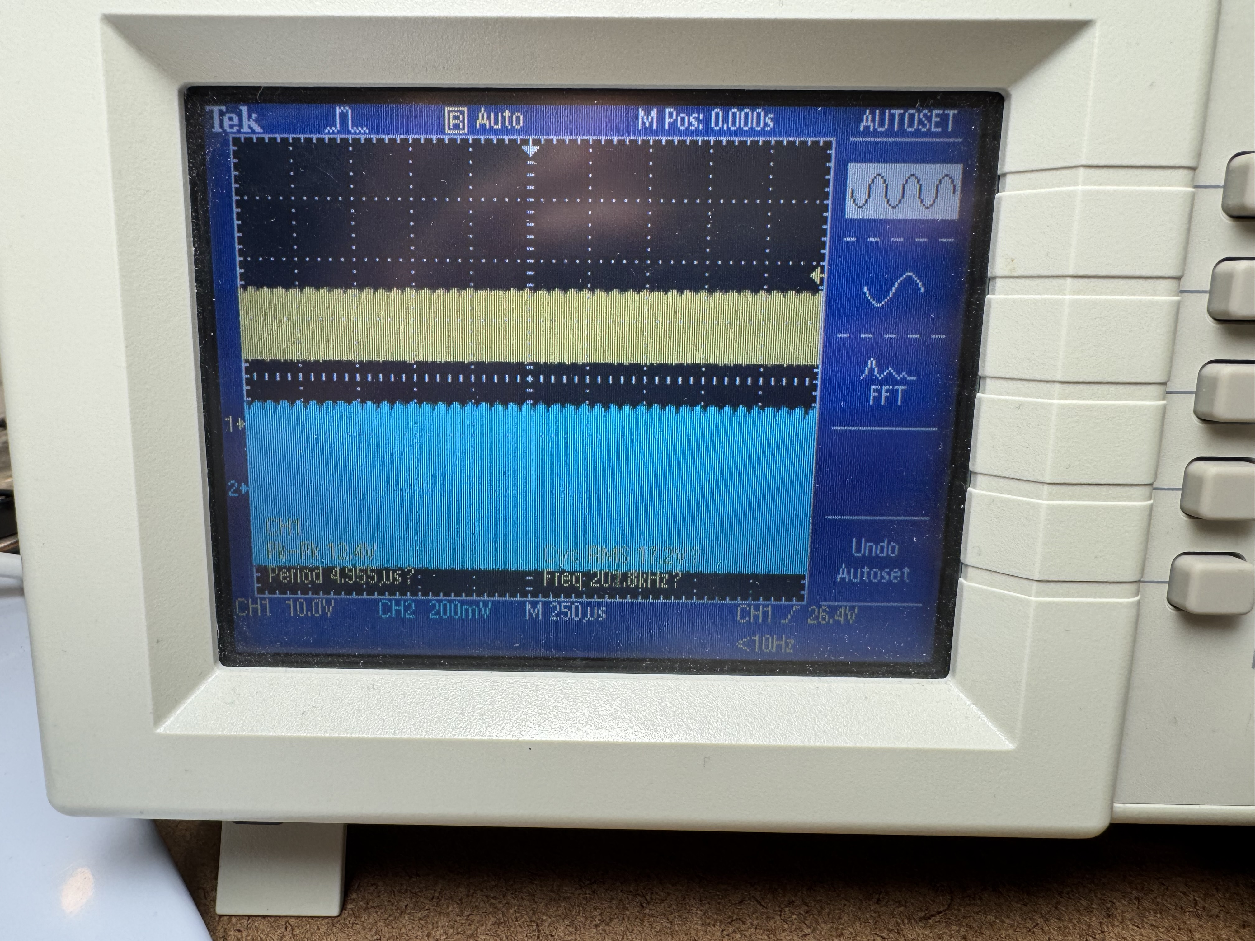
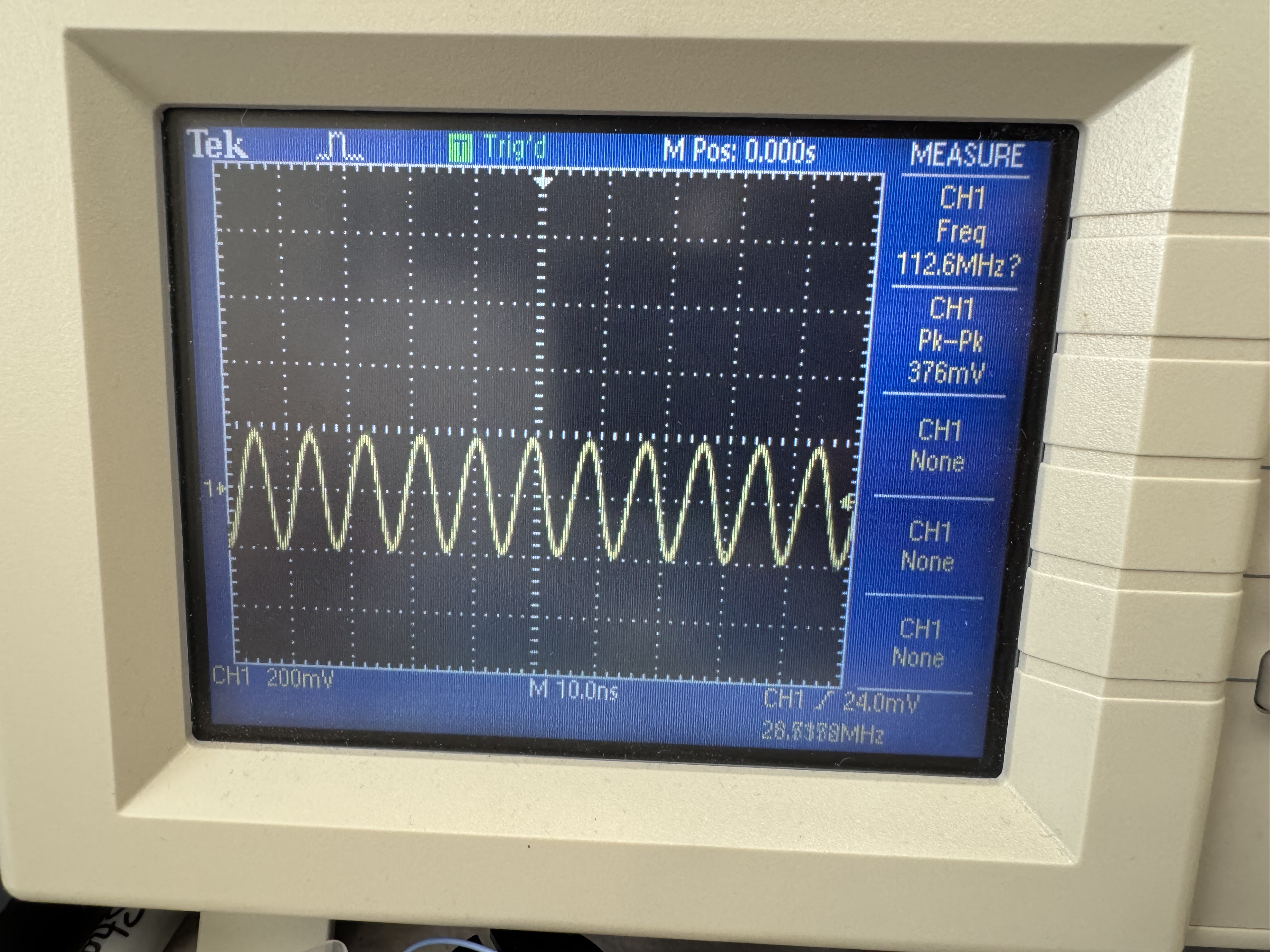
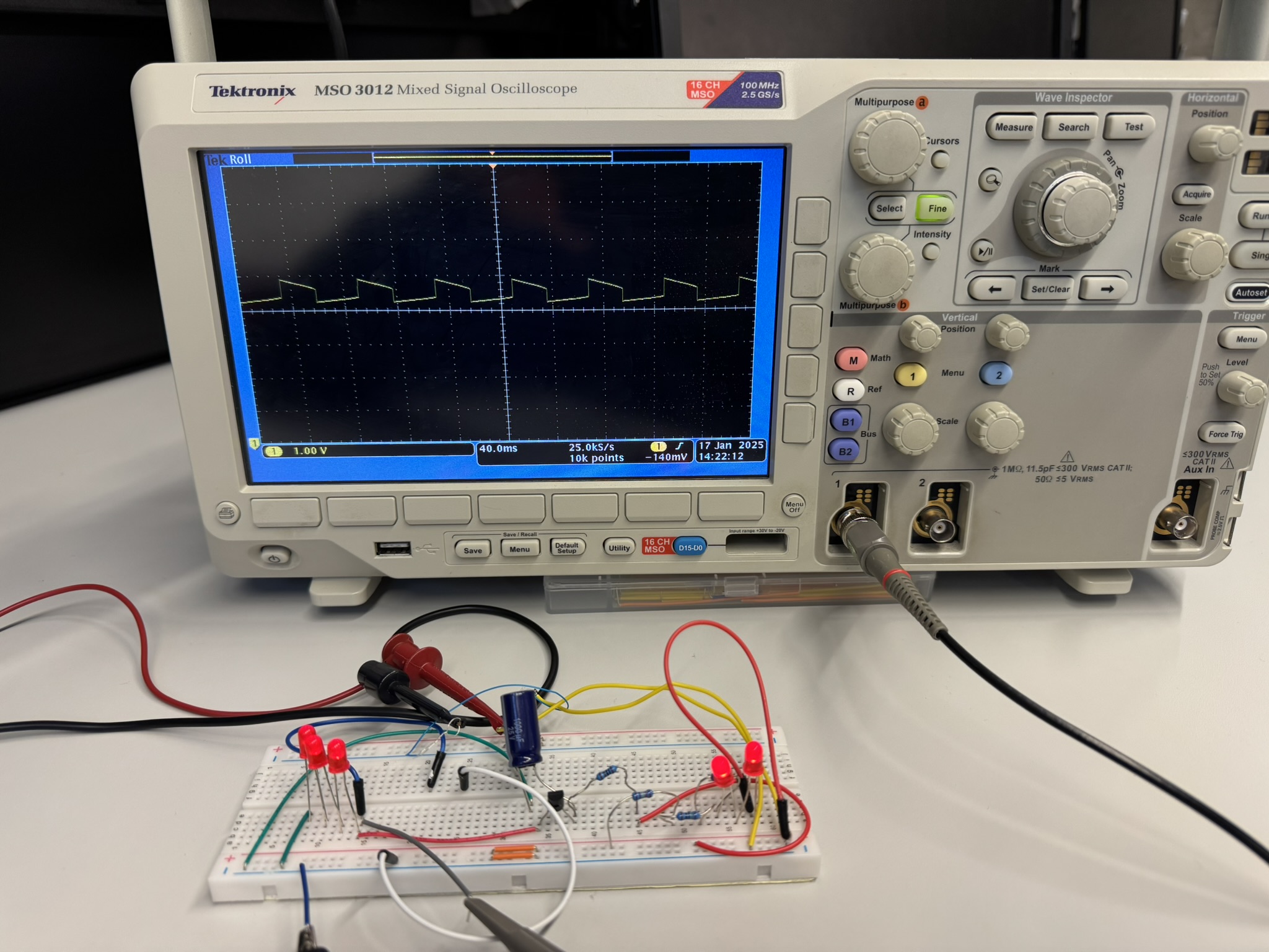
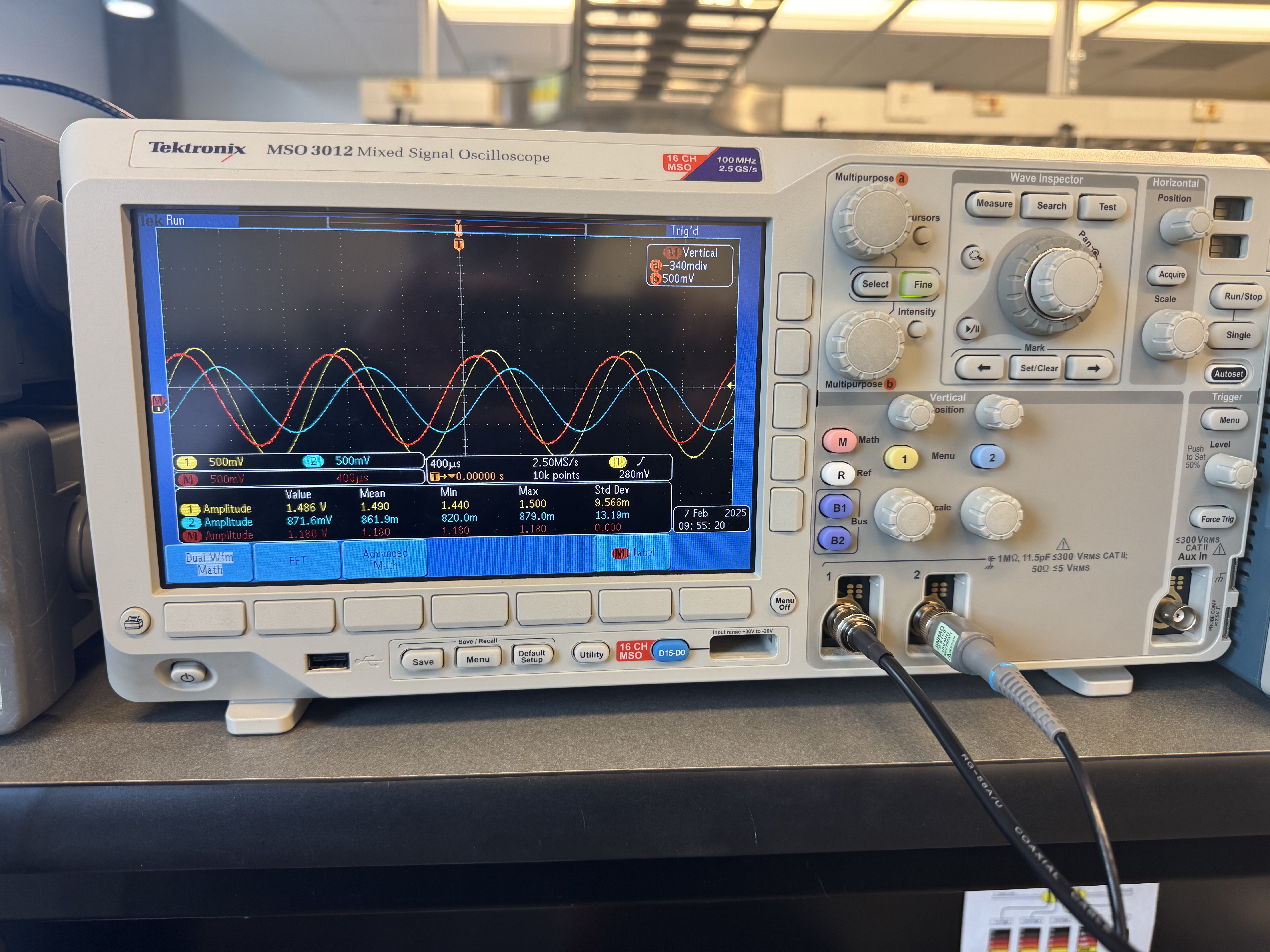
This is the waveform of the transistor oscillator, connected to an oscilloscope. Here a 1000uF capacitor is being used, and a 1K resistor. This is the typical configuration you will see when the transistor oscillator is being used as a “blinker circuit”.
This transistor is a 2n3904. I found it needed about 19 or 20 volts to oscillate. However, transistors such as the 2N2222 only needed around 12V, before they oscillated. So that is interesting, or something I observed. Also, there is a newer version of the 2N2222, the 2N2222A, but I found the standard, or original 2N2222 easier to oscillate. I had both versions.
Faraday Motor (Homopolar Electric Motor)
Video
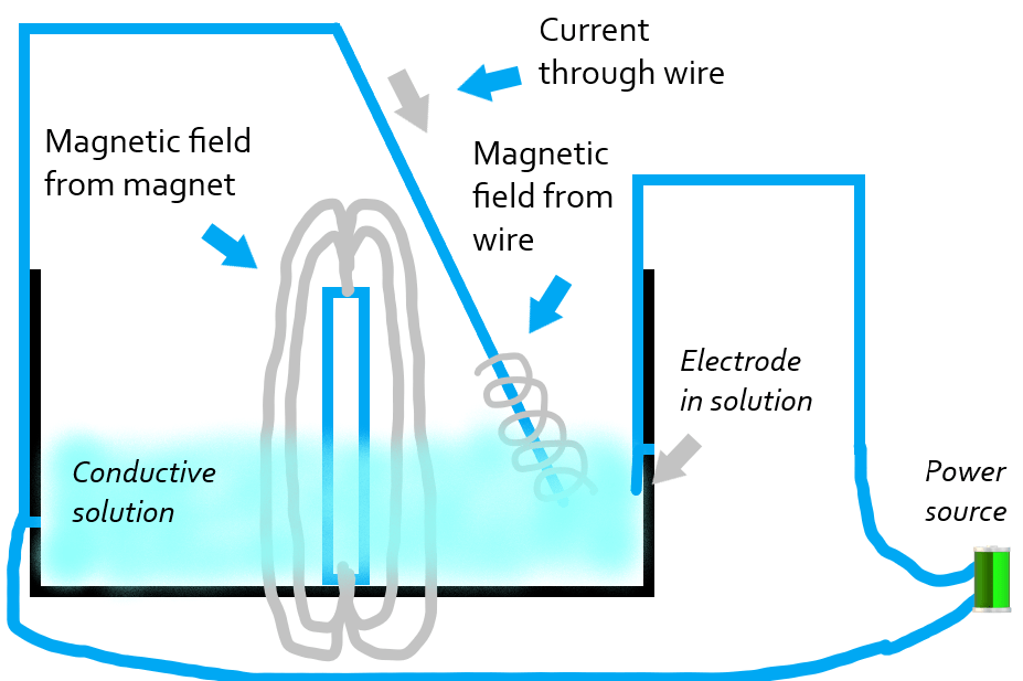
This is the type of motor Faraday made, when he was exploring the connections between magnetism and electricity. It is called a homopolar motor. I just thought it was interesting, because it gives a very intuitive, and visual understanding of the right-hand rule. You could imagine the magnetic field spiraling around the wire. When you change the current direction, the direction of the motor changes.
Pictures
The conductive solution just allows the wire to be energized, without being held captive by anything. This allows us to observe the effects of the magnetic field, when it is energized. I like to think, the wire is ‘riding’, or skirting around the field of the center magnet -which it is. The reason the wire spins around, is due to the circling motion the magnetic field has on the outside of the wire.
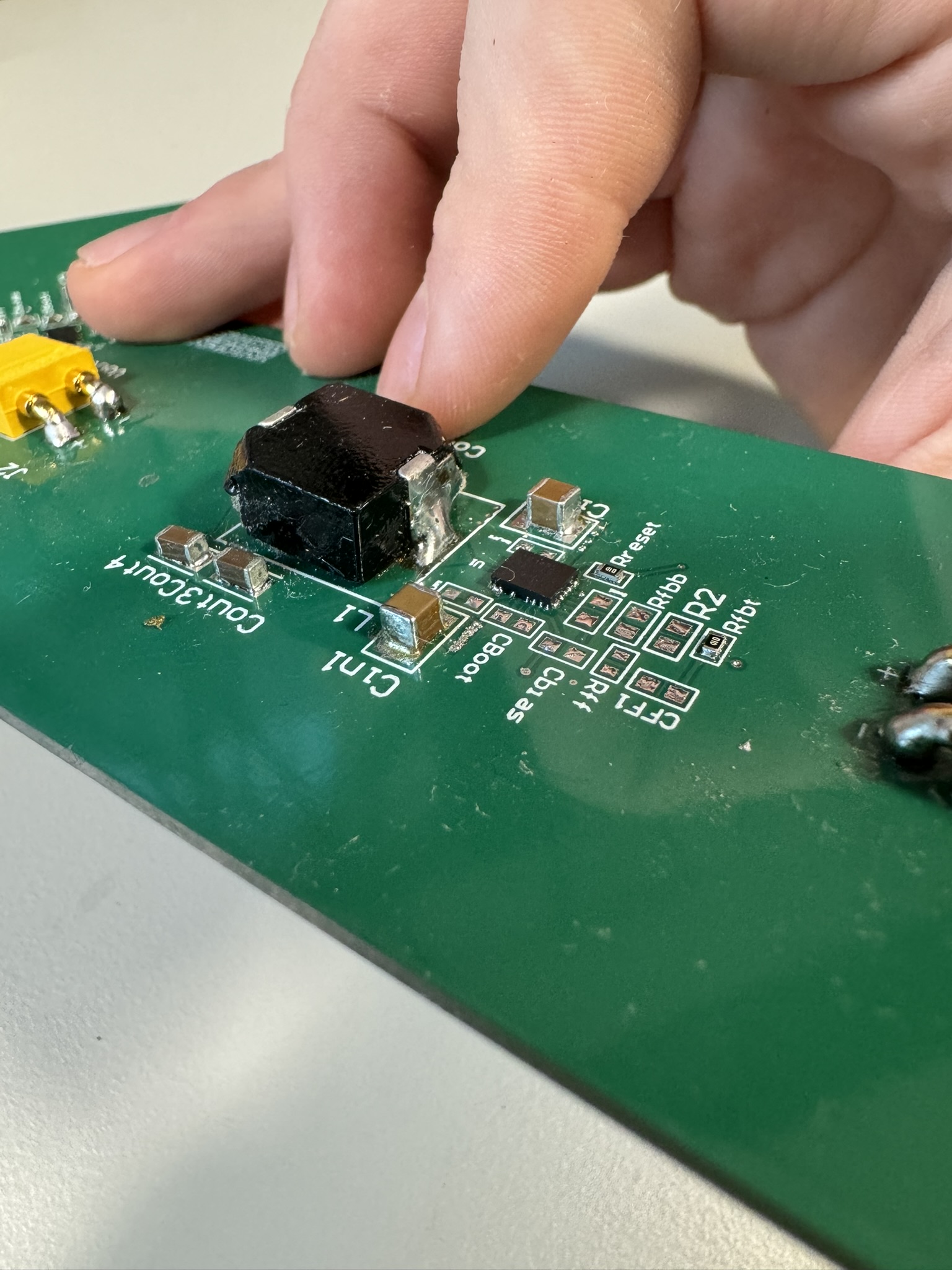
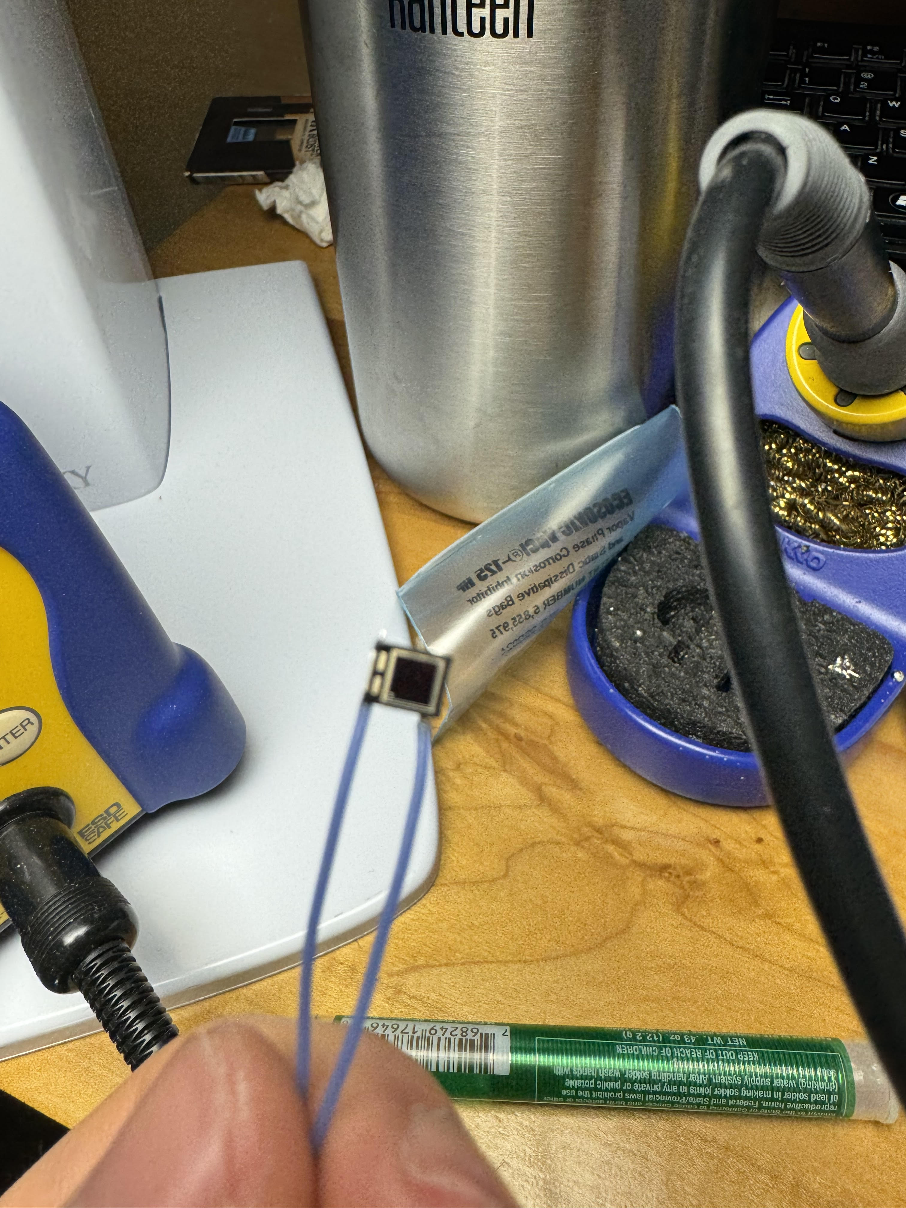
Soldering Experience – QFN, SOIC and SMD
These are just various components, that I’ve soldered. I’ve actually soldered QFN, SOIC, and SMD components. and of course the regular through hole. I didn’t have a breakout board available for that one chip, with the penny. So I soldered small wires to each lead. That is a 16pin soic chip. But I think it just highlights my soldering ability. The silicone is just to hold it still